Arduino DS1307 LCD Clock
Author : Dinesh Kumar Wickramasinghe
Introduction and Images
Hello friends, today I am going to build a Digital Clock using Arduino UNO and famous DS1307 Real Time Clock IC.
Before we begin, here are some images of the completed project. You can find the YouTube video at the bottom of the page.
DS1307 RTC IC
DS1307 is a low power serial real time clock with full binary coded decimal (BCD)
clock/calendar plus 56 bytes of NV SRAM.
The RTC provides year, month, date, hour, minute and second information. The end
date of months is automatically adjusted for months fewer than 31 days including
leap year compensation up to year 2100. It can operate either in 24-hour format
or 12-hour format with AM/PM indicator. Below are the key features of this IC. [1]
- Real-Time Clock (RTC) Counts Seconds, Minutes, Hours, Date of the Month, Month,
Day of the week, and Year with Leap-Year Compensation Valid Up to 2100
- 56-Byte, Battery-Backed, General-Purpose RAM with Unlimited Writes
- I²C Serial Interface
- Programmable Square-Wave Output Signal
- Automatic Power-Fail Detect and Switch Circuitry
- Consumes Less than 500nA in Battery-Backup Mode with Oscillator Running
- Optional Industrial Temperature Range: -40°C to +85°C
- Available in 8-Pin Plastic DIP or SO [2]
The DS1307 IC uses I²C protocol to transfer data to the Microcontroller.
What is I²C Protocol?
I²C (Inter-Integrated Circuit), pronounced I-squared-C, is a multi-master, multi-slave,
single-ended, serial computer bus invented by Philips Semiconductor, known today
as NXP Semiconductors, used for attaching low-speed peripherals to computer motherboards
and embedded systems. Alternatively I²C is spelled I2C (pronounced I-two-C) or IIC
(pronounced I-I-C). [3]
DS1307 Circuit
Before we begin, you have to build a small circuit with some components. Other than
the DS1307 IC, you need following components to build this small circuit. This circuit
is also available as a completed board. You can search on eBay and other famous
electronic shopping web sites for more information.
- 10k Resistors – 2 [pull up resistors]
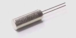
- 32.768 KHz Crystal Oscillator
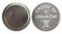
- 3V coin cell battery [to provide backup power]
Please use the following schematic to build the DS1307 circuit [4].
Let’s connect DS1307 circuit to your Arduino UNO
After you completed the above circuit, it is time to connect this circuit to Your
Arduino UNO.
Please use the following configurations table to connect your DS1307 circuit to
Arduino UNO
| DS1307 PIN
|
Arduino PIN
|
Use
|
| 6
|
A5
|
SCL
|
| 5
|
A4
|
SDA
|
| 4
|
Arduino Ground
|
Ground
|
| 8
|
Arduino +5V
|
+5V
|
Following schematic will help you to further understand the pin configurations
The RTClib.h
We are going to use a special library called the RTClib and in it there’s an example
sketch which sets the time on the DS1307 IC. Upon the first power up, the DS1307
will start counting from 1/1/2000 0:00 which is not right, so we need to set it
up to the correct date and time. We’ll only need to do this once as long as the
coin cell battery is not removed. [4]
You can download the library from below Link
Download RTClib
If you are not familiar adding new libraries to Arduino IDE, please follow the tutorial
in below link.
How to add new libraries to Arduino IDE
Source Code for the Step 1
As I mentioned in the introduction of this tutorial, first we are going to test
our real time clock using the Serial Monitor window of the Arduino IDE. Later we
will connect our circuit to a LCD screen.
#include <Wire.h>
#include "RTClib.h"

RTC_DS1307 RTC;

void setup () {
  Serial.begin(9600);
  Wire.begin();
  RTC.begin();

  if (! RTC.isrunning()) {
    Serial.println("RTC is NOT running!");
    RTC.adjust(DateTime(F(__DATE__), F(__TIME__)));
  }
}

void loop () {
    DateTime now = RTC.now();
	Serial.print(now.year(), DEC);
	Serial.print('/');
	Serial.print(now.month(), DEC);
	Serial.print('/');
	Serial.print(now.day(), DEC);
    Serial.print(' ');
    Serial.print(now.hour(), DEC);
    Serial.print(':');
    Serial.print(now.minute(), DEC);
    Serial.print(':');
    Serial.print(now.second(), DEC);
    Serial.println();
    delay(1000);
}
What this code does is basically sets the time and date according to when the sketch
is compiled. Of course there will be a slight delay from the time the code compiles
and it is fully uploaded to the Arduino. I think it’s less of a problem on the newer
Arduinos that are using the Atmel 8U2 and 16U2 as the upload times are significantly
faster.
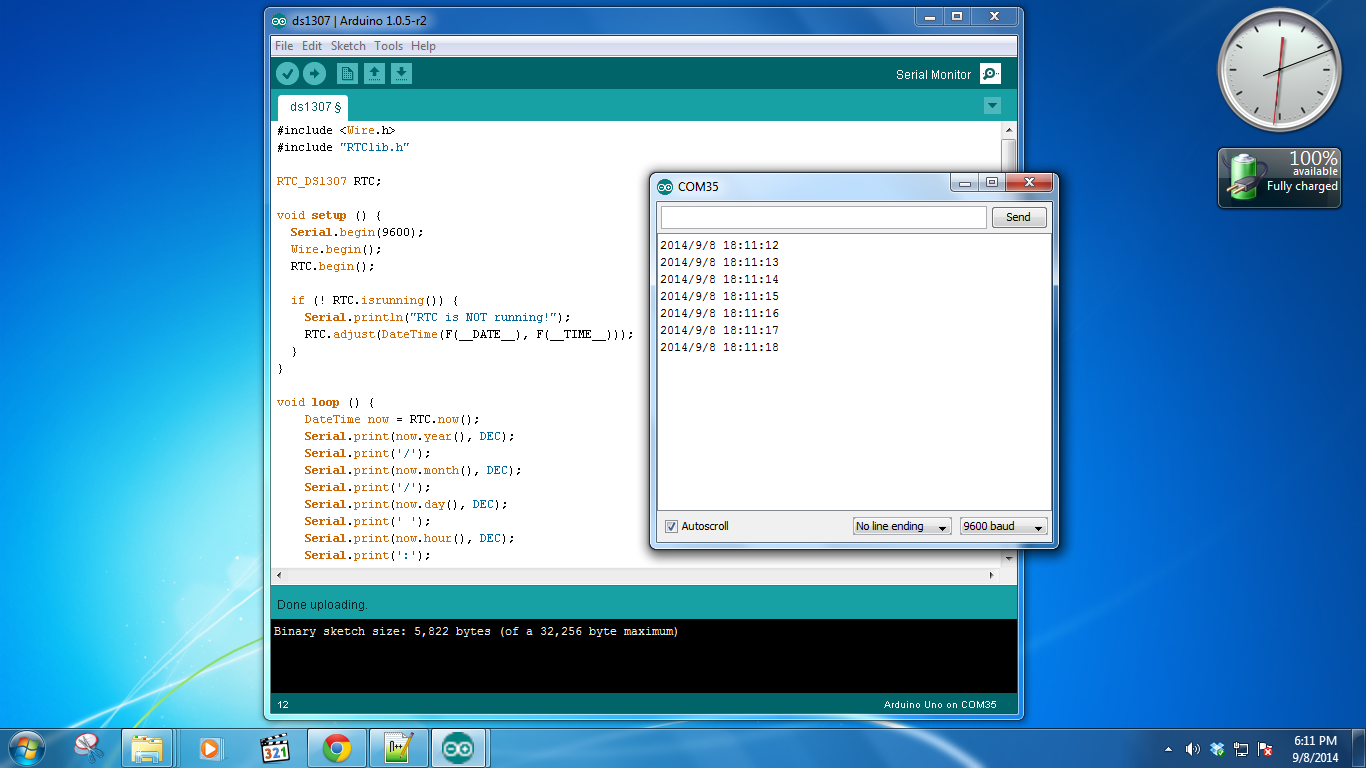
Now open the serial monitor of the Arduino IDE to see the output. Here is a screenshot
of my output. Click on the image to enlarge
Connecting 16x2 LCD Screen to the Project
If you are succeed with the above experiment, now it is time to build a fully working
Digital Clock using a LCD screen. You can use the same circuit you built earlier
in the first step. Only difference is, instead of using the serial monitor, this
time we are going to use a LCD screen to display the time.
Please use the following schematic to connect 16x2 HD44780 compatible LCD screens
to your Arduino UNO board.
Please make sure you keep the previous circuit connections as it is. Connect your
LCD to Arduino. Other than the connections in the above diagram, you have to connect
Ground and +5V connections from LCD to Arduino accordingly
If you are not familiar with connecting LCD screens to Arduino, please refer a tutorial
to update your knowledge
Source Code for the Step 2
Add the following sketch to Arduino IDE and upload it to the Arduino UNO board.
Please compare this code with the previous code, so that you can understand the
differences.
#include <Wire.h>
#include "RTClib.h"
#include <LiquidCrystal.h>

RTC_DS1307 RTC;
LiquidCrystal lcd (7, 8, 9, 10, 11, 12);

void setup () {
  Serial.begin(9600);
  lcd.begin(16, 2);
  Wire.begin();
  RTC.begin();

  if (! RTC.isrunning()) {
    Serial.println("RTC is NOT running!");
    RTC.adjust(DateTime(F(__DATE__), F(__TIME__)));
  }
}

void loop () {
    DateTime now = RTC.now();

    lcd.setCursor(0,0);
    lcd.print("TIME: ");
    lcd.print(now.hour(), DEC);
    lcd.print(":");
    lcd.print(now.minute(), DEC);
    lcd.print(":");
    lcd.print(now.second(), DEC);

    lcd.setCursor(0,1);
    lcd.print("DATE: ");
    lcd.print(now.year(), DEC);
    lcd.print("/");
    lcd.print(now.month(), DEC);
    lcd.print("/");
    lcd.print(now.day(), DEC);

    delay(1000);
}
If you are successfully connect your LCD and upload the above source code, now you
should be able to see the time on your LCD screen. This is the end of this awesome
project. Below you can see the YouTube video of my project.
Conclusion
If you are not familiar with connecting LCD screens to Arduino, please refer some
tutorials to familiar with that.
There are no any push button switches added to the circuit to adjust the time. It
is going beyond the scope of this tutorial. You can try out this in your leisure
time.
In this tutorial, I haven’t described in detail how Arduino actually communicate
with DS1307 via the I2C protocol. Please refer some books or website to understand
the I2C protocol in detail.
If you have any problems, please comment on this page. I will try to help my best.
References
I referred several web pages to create this tutorial. Following are some of them.
You can refer them and update your knowledge.
[1][2]
http://waihung.net/ds1307-real-time-clock-ic/
[3]
http://en.wikipedia.org/wiki/I%C2%B2C
[4]
http://www.electroschematics.com/8921/digital-clock-with-arduino-and-ds1307/
Author - Dinesh Kumar Wickramasinghe